Stromalytix / Biofab Box
Software and robots
for engineered tissues.
For biotech R&D and biomaterials teams turning published methods into experiments they can test. I’m building Stromalytix to connect tissue design, simulation and manufacturing—with the evidence and assumptions visible at each step.
Liver is the first demonstration. The broader goal is a workflow adaptable to different tissues and biomaterials. Biofab Box is the planned hardware component, starting with a donated printer.
See what works today.
Source-linked inputs, cell–matrix and oxygen models, hardware designs, and a lab-workflow mockup.
2:40 · Silent walkthrough with on-screen explanations. The software is demonstrated; printing and biological validation are next.
Choose a chapter, then press Play. Use fullscreen for small text, or open the written walkthrough below. Download the video.
Read the walkthrough
- The software extracts seven experimental inputs from one published liver study, retaining units, source passages, assumptions and missing parameters.
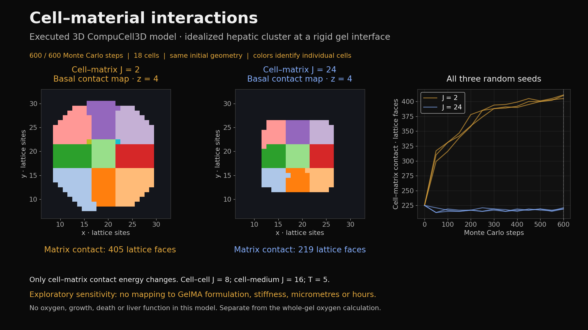
- An executed 3D CompuCell3D sensitivity study compares two assumed cell–matrix contact energies at a rigid gel interface. It uses generic cells, with no mapping to a cell line or material formulation.
- A separate HepG2/C3A reference calculation compares oxygen transport in three whole-gel thicknesses. The models are complementary and are not coupled or reproductions of the preceding paper.
- The oxygen geometry produces fabrication targets and a proposed verification plan. Oxygen, viability and function require their own laboratory measurements.
- The hardware section shows the actual donor printer, followed by conversion, calibration, modular architecture, culture, mechanics and imaging concepts.
- The final mockup illustrates proposed SystemLens and StarNet OS task coordination and a lab digital twin. No live StarNet connection, equipment command or measurement is demonstrated.
What changes at
the cell–matrix interface?
Executed 3D CompuCell3D sensitivity study. A local mechanism experiment for the liver-tissue design context.
A mechanism we can inspect.
At 600 Monte Carlo steps, matrix contact was 405–411 lattice faces for J = 2 and 219–221 for J = 24. Everything else was held fixed. These are ranges across three seeded runs, not confidence intervals.
Cell count, connectedness, volume bounds, matrix stability and exact same-seed repeatability passed numerical checks.
A calibration problem we still own.
The cells and rigid interface are an idealization. No parameter mapping to HepG2/C3A, a GelMA formulation, micrometres, hours or stiffness has been established. This is a complementary sensitivity study, not the same geometry as the oxygen model and not a coupled simulation.
No viability, liver function, drug response or formulation recommendation follows from this demonstration.
One design decision.
Three gel thicknesses.
How does thickness change the oxygen available inside a printed construct?
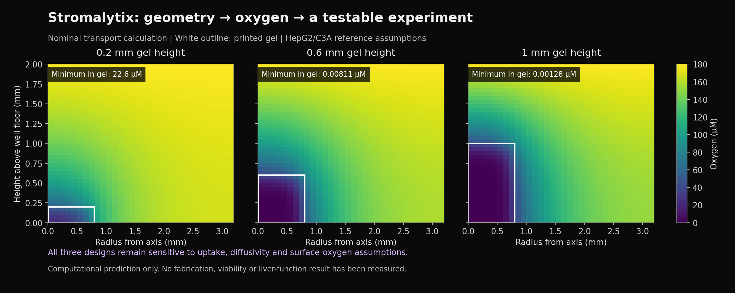
Switches between previously calculated cases. This page does not rerun the solver.
Nominal minimum oxygen in the gel
A prediction to challenge.
This separate reference calculation uses HepG2/C3A assumptions and a GelMA reference material. It models steady oxygen transport and cellular uptake in a static well.
The range reflects eight combinations of uptake, diffusivity and surface-oxygen assumptions. It is not a confidence interval. The next decision is which measurements will narrow those assumptions.
Numerical checks passed for the saved calculation. Physical printing, oxygen measurements, cell viability and liver-function testing have not been performed.
Saved calculation: 67f4272f0fb6bbf3
Inspect model scope and provenance
The model is a 2D axisymmetric finite-volume calculation with Michaelis–Menten oxygen uptake, separate gel and medium diffusivities, fixed surface oxygen, and no-flux walls and floor. It assumes uniformly distributed cells; it does not model growth, death, perfusion or drug response.
The software workflow in the video extracts seven source-linked inputs from a published primary-human-hepatocyte study. This oxygen calculation is a separate HepG2/C3A reference, not a validated prediction of that paper’s experiment.
One build.
Several distinct jobs.
Recovered design iterations and module concepts. These images show proposed hardware, not completed instruments.

Replace filament extrusion with controlled syringe dispensing. Concept; donor conversion is next.
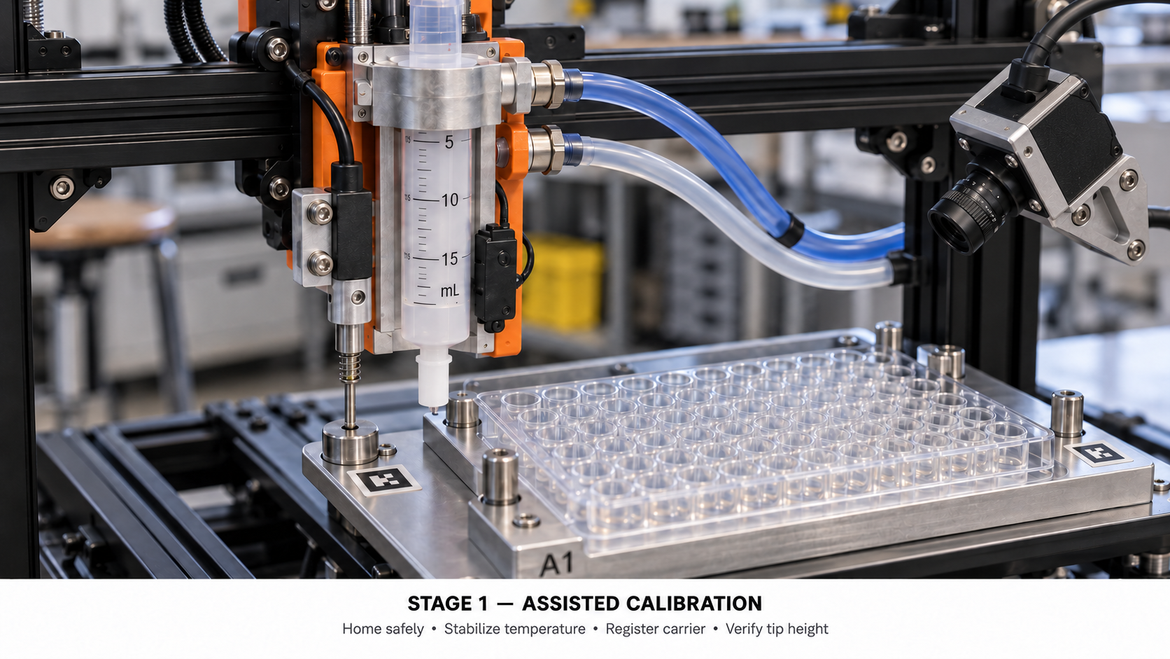
Establish carrier position, nozzle clearance and actual delivered volume. Concept; no calibration result shown.
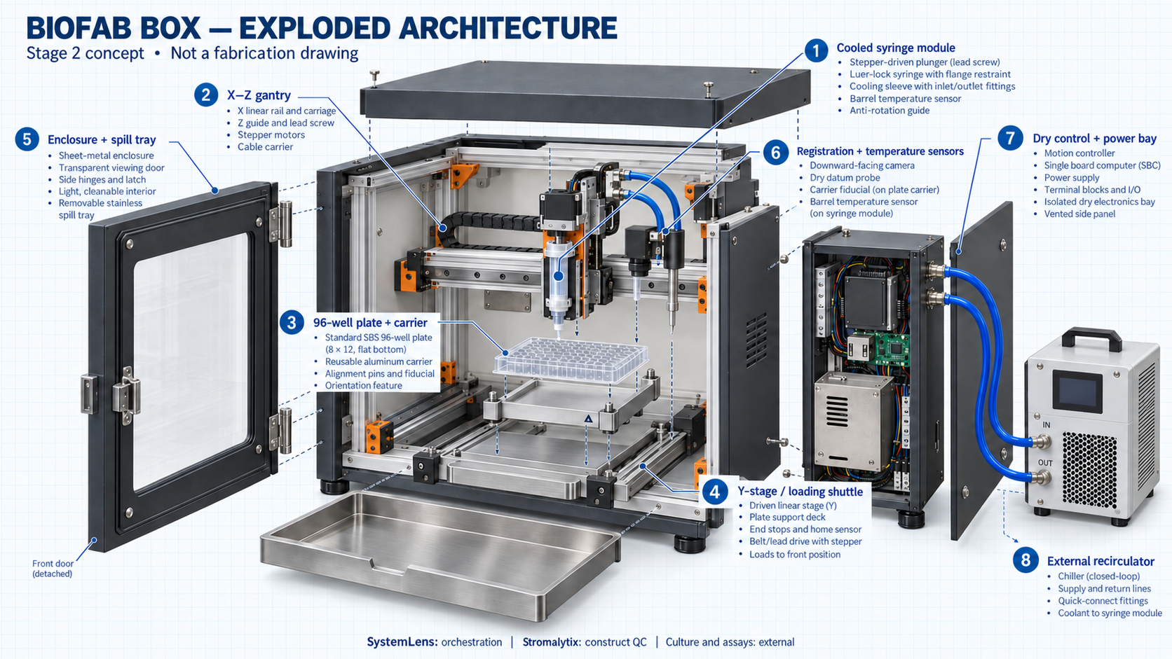
Motion, cooled syringe, carrier, sensing and a separate electronics bay. Design study, not a fabrication drawing.
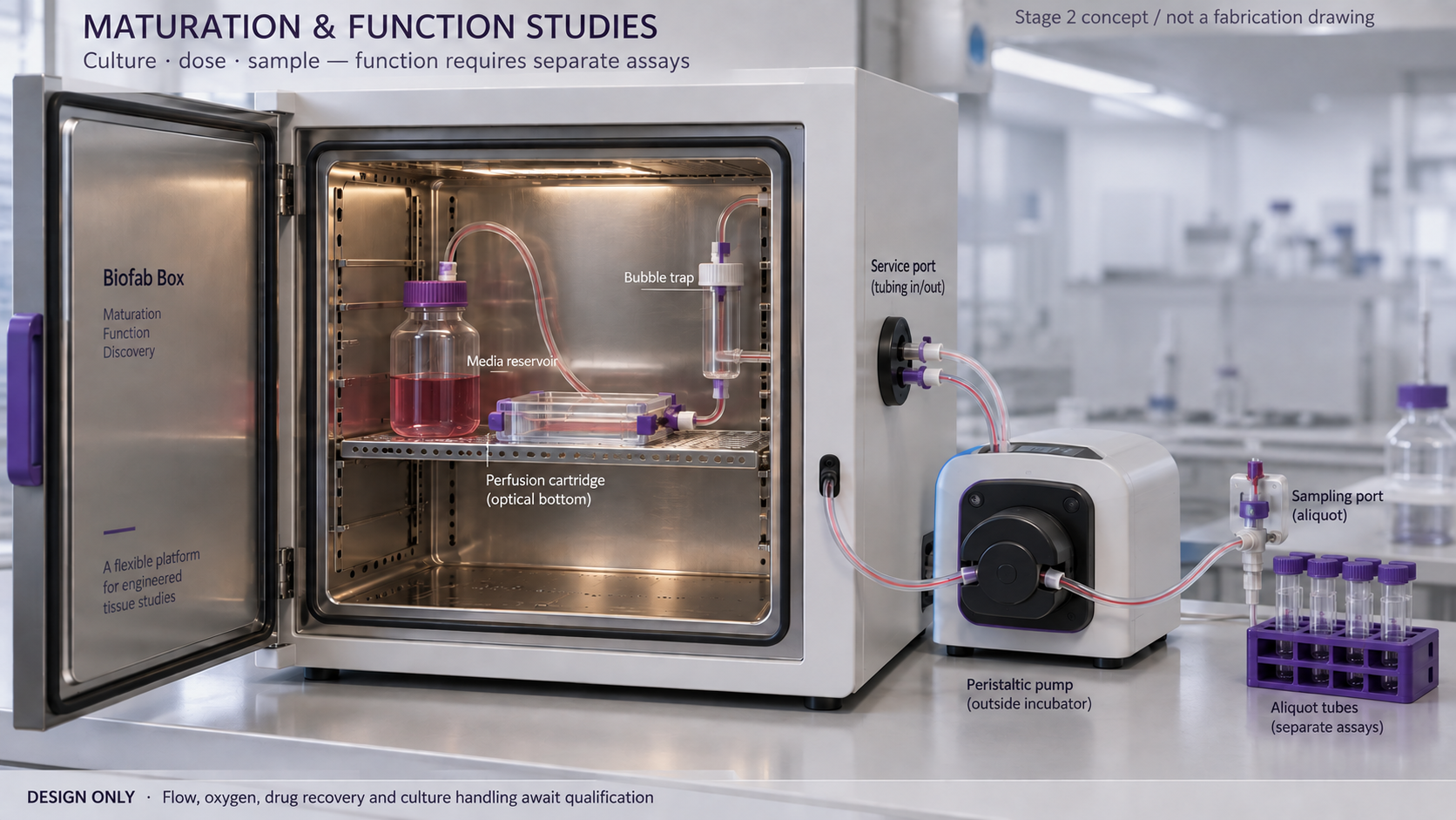
External incubator and a proposed perfusion circuit. Culture handling, flow and drug recovery require qualification.
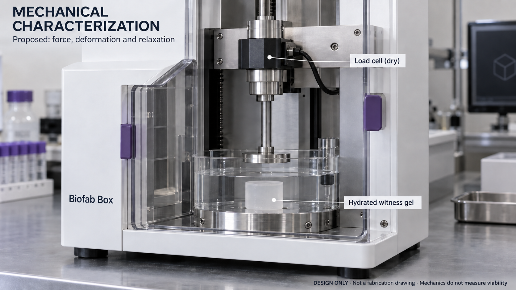
Hydrated witness-gel compression and relaxation. Force, geometry and displacement need calibrated measurements.
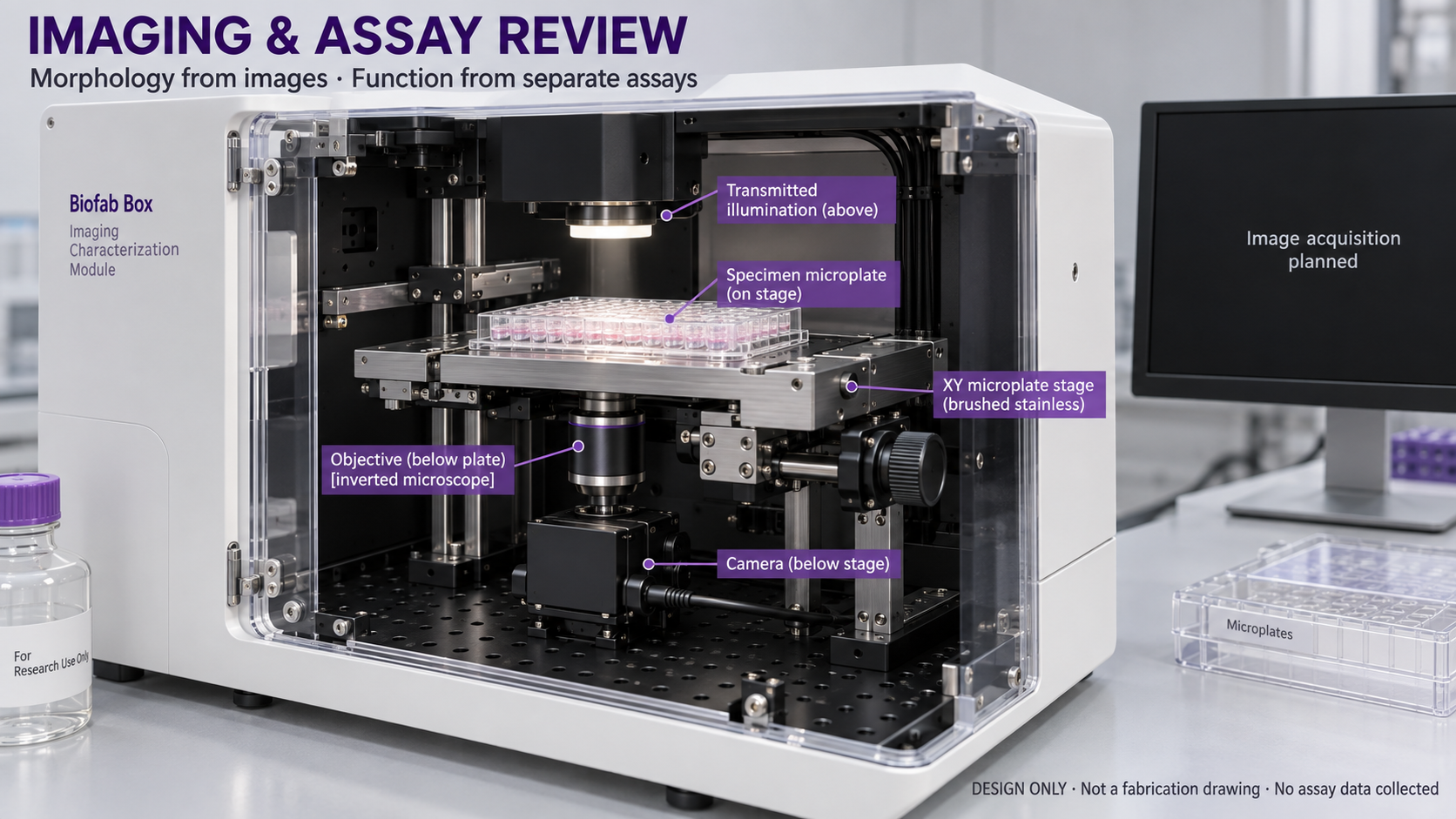
Plate positioning and microscopy concept. Viability and tissue function require separate controlled assays.
The actual donor is a Creality CR-10. Temperature-controlled dispensing, automated registration, perfusion, mechanical testing and imaging integration are design goals. The initial laboratory workflow includes manual transfers.
From a design
to a controlled run.
SystemLens + StarNet OS lab-integration concept. This local mockup illustrates task handoffs and a digital-twin layout; it is not connected to the live StarNet service or laboratory equipment.
Biofab BoxPlanned syringe conversionCulture stationLab access still requiredMeasurement stationOxygen, geometry and assaysStep 1 of 6
Review the saved design
Inspect the 0.2 mm case and its assumptions. Proposed dispensing target: 0.402 µL. No machine command has been sent.
- Mockup opened. No equipment connected.
The intended process record links a sample ID, protocol version, equipment calibration, source artifacts, operator handoffs and eventual raw measurements. This interface demonstrates that planned control flow. Conversion, calibration, validated operating settings and qualified lab access are prerequisites for a physical run. Completing the walkthrough creates no experimental results.
The next proof
comes from the lab.
A proposed verification study exported alongside the geometry and predictions.
Print. Measure. Compare.
- Convert and calibrate the printer with cell-free material; measure dispensing and geometry across independent setups.
- Qualify the cell lot, material, culture conditions and oxygen measurement method with a lab partner.
- Freeze the inputs and predictions, then compare direct oxygen measurements at matching locations.
- Measure viability and tissue function separately, preserve failures, and revise the model when measurements disagree.
Study design, not completed work.
The proposed study has separate 24-hour and day-7 endpoints. Batch is the independent unit. Lab-specific qualification and operating procedures must be completed before execution.
Agreement would support the oxygen model within the tested system. It would not establish drug-safety accuracy or biological function.
Build the next experiment
with a lab partner.
The next milestone is a calibrated printer and measurements that can challenge the saved predictions.
For teams choosing a material.
Biomaterials developers need to connect a formulation and its operating conditions to the experiment it is intended to support. Stromalytix is being built to make those inputs, assumptions and evidence inspectable.
For teams developing a tissue model.
Biotech R&D teams need reproducible experiments and a clear record of what changed. The intended workflow connects design decisions to fabrication and measurement, then uses the results to improve the next design.
The public repository may lag this prototype. The downloadable calculation and protocol above document the run shown here.